Equipment
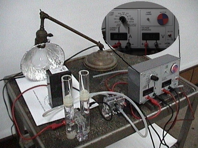
Solar Module, PEM-Electrolyser with storage cylinders, 2 overflow pipes for storage cylinders, PEM Fuel Cell, Load Measurement Box, 2 red cables, 2 black cables, 4 silicone tubes, 3 tubing stoppers, stopwatch, lamp with 100 Watt bulb (maximum), alignment diagram. For a complete picture of the apparatus, see Fig. 1.
Reagents
Distilled or deionized water
Presentation
This kit can perform several functions:
- The solar module converts light into current
- Place the solar module on the alignment diagram so that it is directly over the shaded region of the circle, facing the lamp.
- Place the lamp on the alignment diagram so that the edge of the bulb is over the edge of the bulb diagram.
- Turn on the lamp.
- To measure the current or voltage of the power generated, connect the solar module to the appropriate inputs on the load measurement box using banana clips (optional).
- The current splits water into hydrogen and oxygen in the electrolyser
- Connect the overflow pipes to the gas storage cylinders.
- Fill the O2 and H2 gas storage cylinders to the 0 mL mark with distilled water.
- Connect the solar module to the electrolyser with the banana clips.
- The hydrogen and oxygen are fed into the fuel cell, where they are converted directly into electrical current.
- Connect the electrolyser to the appropriate fuel cell gas inlets using the two long silicone tubes (the gas inlets of the fuel cell are located above the outlets).
- Connect the short silicone tubes to the gas outlets of the fuel cell (located directly below the gas inlets). Both of these tubes should be plugged on the other end.
- Before running the fuel cell, one should collect 5-10 mL of H2 in the hydrogen storage cylinder.
- To initiate a current, unplug the hydrogen outlet tube briefly to allow hydrogen to get to the fuel cell. This can be monitored by watching the bubbles in the silicone tube.
- The current drives the electric motor or the bulb.
- Connect the fuel cell to the current input of the load measurement box using banana clips.
- An additional set of banana clips can be used to measure the voltage produced by the fuel cell.
- Ohm's Law can be demonstrated by varying the resistance and comparing the current and voltage.
- Turn the load to "lamp" to see the lamp light up. It is very faint but take note of the efficiency of the process. A 100 watt bulb can barely light a 12 mW bulb after the power has been converted through these various processes.
- Turn the load to "motor" to see the motor spin. This is much more visible.
- The fuel cell will run as long as the 100 W lamp remains on to produce hydrogen or there is hydrogen remaining in the storage tube. To stop the fuel cell, simply remove its hydrogen supply.
Figure 1
Hazards
Since hydrogen gas is produced in the demonstration, open flames and sparks should be kept away. The lamp generates a lot of heat and could overheat the system if it is placed too close to the solar module. The lamp and solar module should be handled carefully as they could result in skin burns.
Discussion
The chemical reactions involved in these processes are the decomposition, via electrolysis, and reformation, via fuel cell, of water:
The fuel cell works like a battery - the difference is that the fuel cell is constantly supplied with new fuel (H2). At the anode, hydrogen gas is lysed and ionized to protons and electrons (see Fig 2.). These protons pass through the polymer electrolyte membrane (nafion, see Fig 2.) until they find oxygen and ultimately form water. This is the cathode reaction.
Figure 2
The electrons produced at the anode are unable to pass through the polymer electrolyte. Instead they get pushed up out of the cell into a circuit that ultimately connects to the cathode. The current of this circuit can be used to power a motor or a light bulb. The catalysts used in hydrogen fuel cells are usually a mixture of platinum and ruthenium. Platinum provides a surface to which H2(g) can bind. This binding weakens the H-H bond so that lysing and ionization can easily occur (see Fig. 2). A similar process happens at the cathode, facilitating the joining of oxygen, electrons, and protons to form water. The expense of the platinum catalyst is one reason why fuel cells are not yet universal in automobiles. Another drawback is that these catalysts are poisoned over time and eventually lose their activity. The poisoning is the result of sulfur, carbon monoxide, and other contaminants coating the catalytic surface. The solar module's maximum voltage is 2.4V while its maximum generated current is 200 mA. The electrolyser runs on 1.5 V and a current of up to 500 mA. It can produce H2 at a maximum rate of 3.5 mL/min. The fuel cell runs on 0.7 V and can produce a current of 1000 mA. The fuel cell kit comes with multiple manuals for various experiments to explore different aspects of the processes. Calculations can be made to verify Ohm's law, Avogadro's number, and the stoichiometry of water. Feel free to search through them for the experiment best suited for your situation.
References
- Editors: Ted Lister and Henrik Colell, Energy through Hydrogen, research notes, Heliocentris Energiesysteme, GmbH, Berlin, Germany, 2000
- Operating Instructions: Solar Hydrogen Technology Science Kit

